Introduction to Toshiba’s Energy Storage System
Toshiba’s Energy Storage System results from more than 30 years of advanced research and development effort. Central to the system’s world leading capability for grid scale storage applications is the CiB™ batteries.
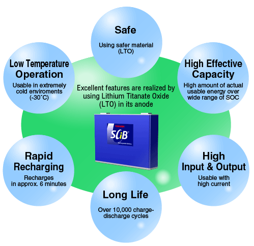
The SCiB™ was initially developed to meet the rigorous demands of electric vehicles. Thus, high energy density, long life and excellent thermal stability are “designed in”. The SCiB™ uses nano-scale lithium titanate in the anode, dramatically improving on standard lithium-ion chemistry and delivering superior performance in terms of:
- Capability to withstand a large number of charge-discharge cycles.
- Rapid charge-discharge rates suitable for high performance applications such as energy storage for frequency response.
- Wide temperature withstand capability suited to operation in extreme environments.
- Extremely low possibility of rupture or ignition, giving excellent safety performance.
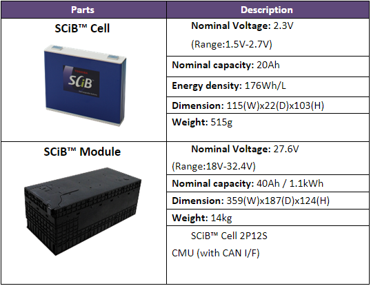
The SCiB™ comprises of the battery cell and module as shown in the table below:
Number of Cells and Configuration (Series/Parallel)
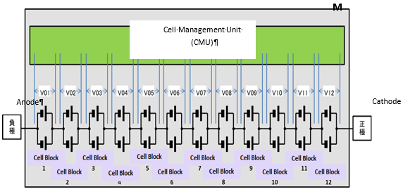
SCiB™ cells have an operational voltage range of 1.8-2.7V, with 20 Ah capacity ;Cells are assembled into a battery module, consisting of 24 cells in a 2P12S (2 cells in parallel and 12 series strings) configuration as shown in Figure 2. The resulting module has 1.1kWh of storage.
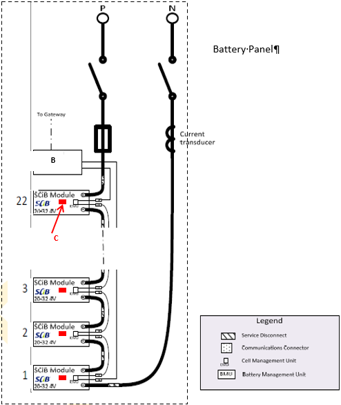
Modules are then arranged into battery panels. Each battery panel consists of 22 modules as shown in Figure 3, for a total of 24kWh.
Battery Management System for Health and Safety of Modules
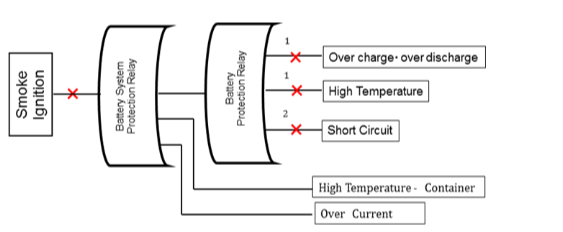
The Battery Management Unit (BMU) will send a warning message when there is an occurrence of an overcharging, over discharging or when temperature is above the safety limits. The BMU will open the contactor automatically to isolate the fault. In addition, once the upper controlling system has detected that the status of the contactor is opened, it will then separate the faulty battery panel from whole system. The battery panels in normal status will continue operation. Also, in the protection of the system from short circuits, fuses are installed.
Cell Management Unit
The Cell Management Unit (CMU) is an internal component of the battery module as shown in Figure 2. The CMU carries out cell voltage balancing in the module, and also collects voltage and temperature readings from the module. It communicates with the BMU via CAN protocol.
By comparing each cell voltage of cells 1 to 12 (in 2P12S module), voltage balancing is performed on each individual cell. The balancer is inactive during the measurement of the voltage in order not to affect the measured voltage values. Upon detection of individual cell or string failure by the CMU, charge/discharge action will be prohibited.
Battery Management Unit
A battery management unit (BMU) is assigned to a battery unit (string) as shown in Figure 3, in which maximum of 22 battery modules can be connected in series. The BMU connects to each CMU and collects cell voltages and temperatures from each battery module. The BMU detects any abnormality of the modules from the collected data and controls the CMUs to protect the battery system. The BMU also measures the total current flowing through a unit by using the current sensor equipped in the unit and conducts cumulated SOC calculation.
Written by Fabio Muzio, from Toshiba